
Kubernetes Networking Deep Dive: Part 2
Pod-to-Pod Communication


This is the second post in a four-part series tracing packets through a Kubernetes cluster. In Part 1, we covered the foundational concepts: network namespaces, veth pairs, CNI, and kube-proxy. Now we trace actual packets between pods.
Pod-to-pod communication is often called “east-west traffic” and is the most common network traffic in a cluster. A pod connects to a service, a microservice calls another, in-cluster databases receive queries from application pods, etc. This traffic stays within the cluster and does not go through a load balancer.
Let’s look at two scenarios: pods on the same node (communication through a bridge) and pods on different nodes (requiring overlay encapsulation or direct routing).
Scenario Setup
For upcoming examples, let’s use the following setup:
Pod A: IP 10.244.0.5, running on Node 1 (192.168.1.10)
Pod B: IP 10.244.0.6, also running on Node 1
Pod C: IP 10.244.1.5, running on Node 2 (192.168.1.11)
Pod A runs a client application. Pod B and Pod C each run a server listening on port 8080. Let’s trace what happens when Pod A makes an HTTP request to Pod B (on the same node) and then to Pod C (on a different node).
Pod-to-Pod Communication on the Same Node
When two pods are running on the same node, the network traffic never leaves the host. The packet travels via the Linux bridge (that acts as a virtual switch on each node) connecting all the local pod veth endpoints.
Packet Flow Steps
Step 1: Application makes connection (OSI Layer 7)
The application in Pod A calls the connect() system call to establish a TCP connection to 10.244.0.6:8080. (A standard socket operation)
Step 2: Kernel starts building the TCP/IP packet (OSI Layers 4 and 3)
The kernel’s TCP/IP stack creates the packet:
Source IP: 10.244.0.5
Destination IP: 10.244.0.6
Source port: ephemeral, chosen by the OS (e.g., 45678)
Destination port: 8080
Protocol: TCP
Step 3: Routing is decided in Pod A’s networking namespace (OSI Layer 3)
The kernel looks at Pod A’s routing table to determine the outgoing interface:
# Inside Pod A
ip route

# Output:
# default via 10.244.0.1 dev eth0
# 10.244.0.0/24 dev eth0 proto kernel scope link src 10.244.0.5
The destination 10.244.0.6 matches the 10.244.0.0/24 route, which says “send directly via eth0.” A gateway is not needed because the destination is on the same subnet.
Step 4: ARP resolution (Layer 2)
Before sending the packet, the kernel will need the MAC address of 10.244.0.6. It checks the ARP** ( cache (a.k.a. Neighbor Table) or sends an ARP request:
# Inside Pod A's namespace;
ip neigh show

# Output:
# 10.244.0.6 dev eth0 lladdr 62:a1:b2:c3:d4:e6 REACHABLE
# 10.244.0.1 dev eth0 lladdr 8a:1b:2c:3d:4e:5f REACHABLE
The kernel builds an Ethernet frame with:
Source MAC: Pod A’s eth0 MAC
Destination MAC: Pod B’s eth0 MAC (62:a1:b2:c3:d4:e6)
**ARP = Address Resolution Protocol: For discovery of OSI Layer 2 (MAC) address.
Step 5: Packet leaves Pod A via veth pair (OSI Layer 2)
The frame exits through Pod A’s eth0, which is one end of a veth pair. The packet emerges from the other end (veth-pod-a) in the node’s namespace.
Step 6: Bridge forwards the frame (OSI Layer 2)
The host-side veth is attached to a bridge (commonly named cni0, cbr0, or docker0 depending on CNI). The bridge operates like a Layer 2 switch:
It receives the frame on port veth-pod-a
It looks up the destination MAC in its forwarding table
It finds that MAC 62:a1:b2:c3:d4:e6 is reachable on port veth-pod-b
It forwards the frame out that port
You can view the bridge’s MAC table:
# On the host (FDB = Forwarding Database)
bridge fdb show br cni0 | grep -i "62:a1"

# Output:
# 62:a1:b2:c3:d4:e6 dev veth-pod-b master cni0
Step 7: Packet enters Pod B via veth pair (OSI Layer 2)
The frame enters veth-pod-b in the host namespace and emerges from eth0 in Pod B’s namespace.
Step 8: Kernel delivers to application (OSI Layers 3, 4, 7 → Back up the OSI stack)
Pod B’s kernel:
Receives the packet
Takes out the the Ethernet header (no longer needed), sees that it is an IP packet
Verifies that the destination IP matches its own (10.244.0.6)
Gets rid of the IP header (no longer needed here), sees it is TCP and destined for port 8080
Delivers the payload to the application listening on that port
The return traffic (Pod B’s response) follows the same path in reverse.
Observing Same-Node Traffic
You can check out this traffic at different points:
# Capture on the bridge (sees ALL local pod traffic)
sudo tcpdump -i cni0 -nn host 10.244.0.5 and host 10.244.0.6

# Output:
# 14:23:01.234567 IP 10.244.0.5.45678 > 10.244.0.6.8080: Flags [S], seq 123456789
# 14:23:01.234789 IP 10.244.0.6.8080 > 10.244.0.5.45678: Flags [S.], seq 987654321, ack 123456790

# Capture on a specific veth (sees only that pod's traffic, great for troubleshooting)
sudo tcpdump -i veth-pod-a -nn port 8080
iptables’ Involvement
For direct pod-to-pod communication (not through a Service), iptables is not heavily involved. The packet passes through the FORWARD chain in the filter table, but unless you have NetworkPolicies configured, the default is to ACCEPT.
Another fun iptables command for you:
sudo iptables -L FORWARD -n -v | head -5
# Output:
# Chain FORWARD (policy ACCEPT 0 packets, 0 bytes)
#  pkts bytes target     prot opt in     out     source               destination
#  1.2M  890M KUBE-FORWARD  all  --  *      *       0.0.0.0/0            0.0.0.0/0
#  1.2M  890M CNI-FORWARD   all  --  *      *       0.0.0.0/0            0.0.0.0/0
The CNI-FORWARD chain generally contains rules for NetworkPolicy enforcement if your CNI supports it (note that not all do!)
Cross-Node Pod-to-Pod Traffic
When pods are on different nodes, the packet has to travel on the physical network connecting the two nodes. This is where the capabilities of the CNI plugin matters. Let’s take a high-level look at both overlay (VXLAN) and routed (BGP) approaches.
The Central Problem
Node 1 has a packet destined for 10.244.1.5 (Pod C on Node 2). The physical network between nodes has no information about pod IP addresses. It only knows how to route traffic between node IP addresses (192.168.1.10 and 192.168.1.11).
We have two solutions:
Overlay: Encapsulate the pod-to-pod packet inside a node-to-node packet
Routed: Configure the physical network to route the pod CIDRs themselves
Cross-Node Communication: Overlay (VXLAN)
VXLAN (Virtual Extensible LAN) creates a Layer 2 overlay on top of a Layer 3 network. Eek, what’s that?
Well, pod traffic is encapsulated in UDP packets sent between nodes.
Step-by-Step Packet Flow
Step 1: Application initiates connection (OS Layer 7)
Pod A’s application connects to 10.244.1.5:8080 (Pod C). Standard socket connection like above.
Step 2: Kernel builds the TCP/IP packet (OSI Layers 4 and 3)
Source IP: 10.244.0.5
Destination IP: 10.244.1.5
Source ephemeral port: 45678
Destination port: 8080
Step 3: Routing decision done in Pod A’s namespace (OSI Layer 3)
# Inside Pod A
ip route

# Output:
# default via 10.244.0.1 dev eth0
# 10.244.0.0/24 dev eth0 proto kernel scope link src 10.244.0.5
The destination 10.244.1.5 does not match 10.244.0.0/24, so the packet will go to the default gateway (10.244.0.1).
Step 4: Packet reaches host namespace via veth
The packet exits eth0 in Pod A, and emerges from veth-pod-a in the host namespace.
Step 5: Host’s routing table lookup (OSI Layer 3)
The host’s kernel takes a look at its routing table:
# On Node 1
ip route

# Output (Flannel VXLAN example):
# default via 192.168.1.1 dev eth0
# 10.244.0.0/24 dev cni0 proto kernel scope link src 10.244.0.1
# 10.244.1.0/24 via 10.244.1.0 dev flannel.1 onlink
# 10.244.2.0/24 via 10.244.2.0 dev flannel.1 onlink
The destination 10.244.1.5 matches 10.244.1.0/24 via flannel.1. (if that’s the CNI you’re using, but note that the Flannel CNI does not have NetworkPolicy capabilities). The flannel.1 interface is a VXLAN Tunnel Endpoint (VTEP).
Step 6: VXLAN encapsulation (OSI Layer 2 over Layer 3)
The flannel.1 interface:
Looks up which node owns 10.244.1.0/24 (Node 2 in our case: 192.168.1.11)
It then encapsulates the original Ethernet frame within a VXLAN header
It wraps that in a UDP packet (destination port 4789)
And finally it’s wrapped in an IP packet (192.168.1.10 to 192.168.1.11)
You can see the VXLAN FDB (forwarding database):
# On Node 1
bridge fdb show dev flannel.1

# Output:
# 5a:2b:3c:4d:5e:6f dst 192.168.1.11 self permanent
# 7a:8b:9c:0d:1e:2f dst 192.168.1.12 self permanent
This maps the VTEP MAC addresses to node IPs.
Step 7: Outer packet sent to Node 2 (Layers 3 and 2)
The encapsulated packet is then routed normally over the network like any other packet going between nodes to 192.168.1.11:
Source IP: 192.168.1.10 (Node 1)
Destination IP: 192.168.1.11 (Node 2)
Protocol: UDP
Destination port: 4789 (VXLAN)
Payload: VXLAN header + original Ethernet frame
Step 8: Node 2 receives and removes the encapsulation (OSI Layer 3)
Node 2’s kernel:
Receives UDP packet on port 4789
Recognizes it as VXLAN traffic for the flannel.1 interface
Nixes the Ethernet, IP, UDP, and VXLAN headers (tear that envelope open!)
Extracts the original Ethernet frame
Step 9: Host routing to the destination local pod (Layer 3)
The extracted packet has destination 10.244.1.5. Node 2’s routing table:
# On Node 2
ip route

# Output:
# 10.244.1.0/24 dev cni0 proto kernel scope link src 10.244.1.1
A local route so the packet goes to the cni0 bridge.
Step 10: Bridge forwards to Pod C (Layer 2)
The bridge looks up the MAC address for 10.244.1.5 and forwards the frame to veth-pod-c.
Step 11: Pod C receives packet (Layers 3, 4, 7)
The packet enters Pod C’s namespace through eth0. The kernel delivers it to the application on port 8080.
VXLAN Packet Structure
At step 7, the packet on the wire looks something like this. (Yeah a bit in the weeds. I had help drawing this.)
┌────────────────────────────────────────────────────────────────────────────┐
│                    VXLAN ENCAPSULATED PACKET                               │
├───────────────┬────────────────┬──────────┬────────┬──────────┬───────────┤
│ Outer         │ Outer IP       │ UDP      │ VXLAN  │ Inner    │ Inner IP  │
│ Ethernet      │ Header         │ Header   │ Header │ Ethernet │ Packet    │
├───────────────┼────────────────┼──────────┼────────┼──────────┼───────────┤
│ dst: router   │ src: 192.168.  │ src:     │ VNI:   │ dst: Pod │ src:      │
│ MAC           │ 1.10           │ random   │ 1      │ C MAC    │ 10.244.   │
│               │ dst: 192.168.  │ dst:     │        │ src: Pod │ 0.5       │
│ src: Node1    │ 1.11           │ 4789     │        │ A MAC    │ dst:      │
│ MAC           │                │          │        │          │ 10.244.   │
│               │                │          │        │          │ 1.5       │
├───────────────┼────────────────┼──────────┼────────┼──────────┼───────────┤
│    14 bytes   │    20 bytes    │  8 bytes │8 bytes │ 14 bytes │ 20+ bytes │
└───────────────┴────────────────┴──────────┴────────┴──────────┴───────────┘
                │                                    │
                │◄──────── 50 bytes overhead ───────►│

Total overhead: 50 bytes (outer Ethernet + outer IP + UDP + VXLAN + inner Ethernet)
This is why pod MTU is typically 1450 when node MTU is 1500.
Viewing VXLAN Traffic
# On Node 1, capture VXLAN-encapsulated traffic
sudo tcpdump -i eth0 -nn udp port 4789

# Output:
# 14:30:01.123 IP 192.168.1.10.52341 > 192.168.1.11.4789: VXLAN, flags [I] (0x08), vni 1
# IP 10.244.0.5.45678 > 10.244.1.5.8080: Flags [S], seq 123456789

# Capture on the VXLAN interface (sees non-encapsulated traffic)
sudo tcpdump -i flannel.1 -nn host 10.244.1.5

# Output:
# 14:30:01.123 IP 10.244.0.5.45678 > 10.244.1.5.8080: Flags [S], seq 123456789
Cross-Node Communication: Routed (BGP)
In routed (BGP***) mode, there is no encapsulation. Pod IPs are advertised via BGP (or even static routes) so the physical network knows how to route them.
Prerequisites
Routed mode requires one of:
BGP peering
between nodes and network routers
between nodes themselves
Static routes configured on network infrastructure
Cloud VPC route table entries
***BGP = Border Gateway Protocol: standardized gateway protocol to exchange routing and reachability information among autonomous systems
Step-by-Step Packet Flow
Steps 1-4: Same as overlay
Pod A builds a packet for 10.244.1.5, it exits via veth to the host namespace.
Step 5: Host routing table lookup (Layer 3)
Notice that the host’s routing table in BGP mode looks a bit different:
# On Node 1 (Calico BGP mode)
ip route

# Output:
# default via 192.168.1.1 dev eth0
# 10.244.0.0/24 dev cni0 proto kernel scope link src 10.244.0.1
# 10.244.1.0/24 via 192.168.1.11 dev eth0 proto bird
# 10.244.2.0/24 via 192.168.1.12 dev eth0 proto bird
The route for 10.244.1.0/24 points directly to Node 2’s IP (192.168.1.11) via the physical interface (eth0 - on the host, not to be confused with a pod’s eth0). The proto bird indicates these routes were installed by the BIRD BGP daemon used by Calico CNI (for this example).
Step 6: Packet sent to Node 2 (OSI Layer 3)
The packet is sent directly with:
Source IP: 10.244.0.5 (Pod A, unchanged)
Destination IP: 10.244.1.5 (Pod C, unchanged)
At Layer 2:
Source MAC: Node 1’s eth0
Destination MAC: Next hop (a router or Node 2 if on same Layer 2 network segment. In this case it’s the same segment.)
Remember that there is no encapsulation. The pod IPs are visible on the physical network.
Step 7: Physical network routing
The physical network needs to know how to route 10.244.1.0/24 to Node 2. This happens via:
BGP: Nodes advertise their pod CIDRs. Routers learn the routes.
Static routes: Network admin configures routes on routers (I’m not fond of static routing. It makes maintenance tougher.)
Cloud VPC: Cloud provider handles the routing.
Step 8: Node 2 receives packet (OSI Layer 3)
Node 2 receives a packet with destination 10.244.1.5. Its routing table:
# On Node 2
ip route

# Output:
# 10.244.1.0/24 dev cni0 proto kernel scope link src 10.244.1.1
The destination is local so route to cni0 bridge.
Steps 9-10: Same as with overlay
Bridge forwards to Pod C. Application receives the packet.
Observing BGP Routes
Again, in the weeds.
# View BGP-learned routes (Calico with BIRD)
sudo calicoctl node status

# Output:
# IPv4 BGP status
# +--------------+-------------------+-------+----------+-------------+
# | PEER ADDRESS |     PEER TYPE     | STATE |  SINCE   |    INFO     |
# +--------------+-------------------+-------+----------+-------------+
# | 192.168.1.11 | node-to-node mesh | up    | 10:23:45 | Established |
# | 192.168.1.12 | node-to-node mesh | up    | 10:23:47 | Established |
# +--------------+-------------------+-------+----------+-------------+

# View routes learned via BGP
ip route show proto bird

# Output:
# 10.244.1.0/24 via 192.168.1.11 dev eth0
# 10.244.2.0/24 via 192.168.1.12 dev eth0

# Capture unencapsulated pod traffic on physical interface
sudo tcpdump -i eth0 -nn host 10.244.1.5

# Output:
# 14:35:01.234 IP 10.244.0.5.45678 > 10.244.1.5.8080: Flags [S], seq 123456789
IPinIP: A Lighter Overlay
Some CNIs (notably Calico) support IPinIP as a lighter-weight alternative to VXLAN. IPinIP encapsulates the original IP packet directly in another IP packet, without the UDP and VXLAN headers.
┌────────────────────────────────────────────────────────────────┐
│                    IPINIP PACKET                               │
├───────────────┬────────────────┬───────────────────────────────┤
│ Outer         │ Outer IP       │ Inner IP Packet               │
│ Ethernet      │ Header         │ (original pod-to-pod packet)  │
├───────────────┼────────────────┼───────────────────────────────┤
│ dst: router   │ src: 192.168.  │ src: 10.244.0.5               │
│ MAC           │ 1.10           │ dst: 10.244.1.5               │
│               │ dst: 192.168.  │ + TCP header + payload        │
│               │ 1.11           │                               │
│               │ proto: 4 (IPIP)│                               │
├───────────────┼────────────────┼───────────────────────────────┤
│    14 bytes   │    20 bytes    │         20+ bytes             │
└───────────────┴────────────────┴───────────────────────────────┘

Overhead: 20 bytes (just the outer IP header)
Pod MTU can be 1480 instead of 1450.
Calico can use IPinIP for cross-subnet traffic and direct routing for same-subnet traffic (”CrossSubnet” mode).
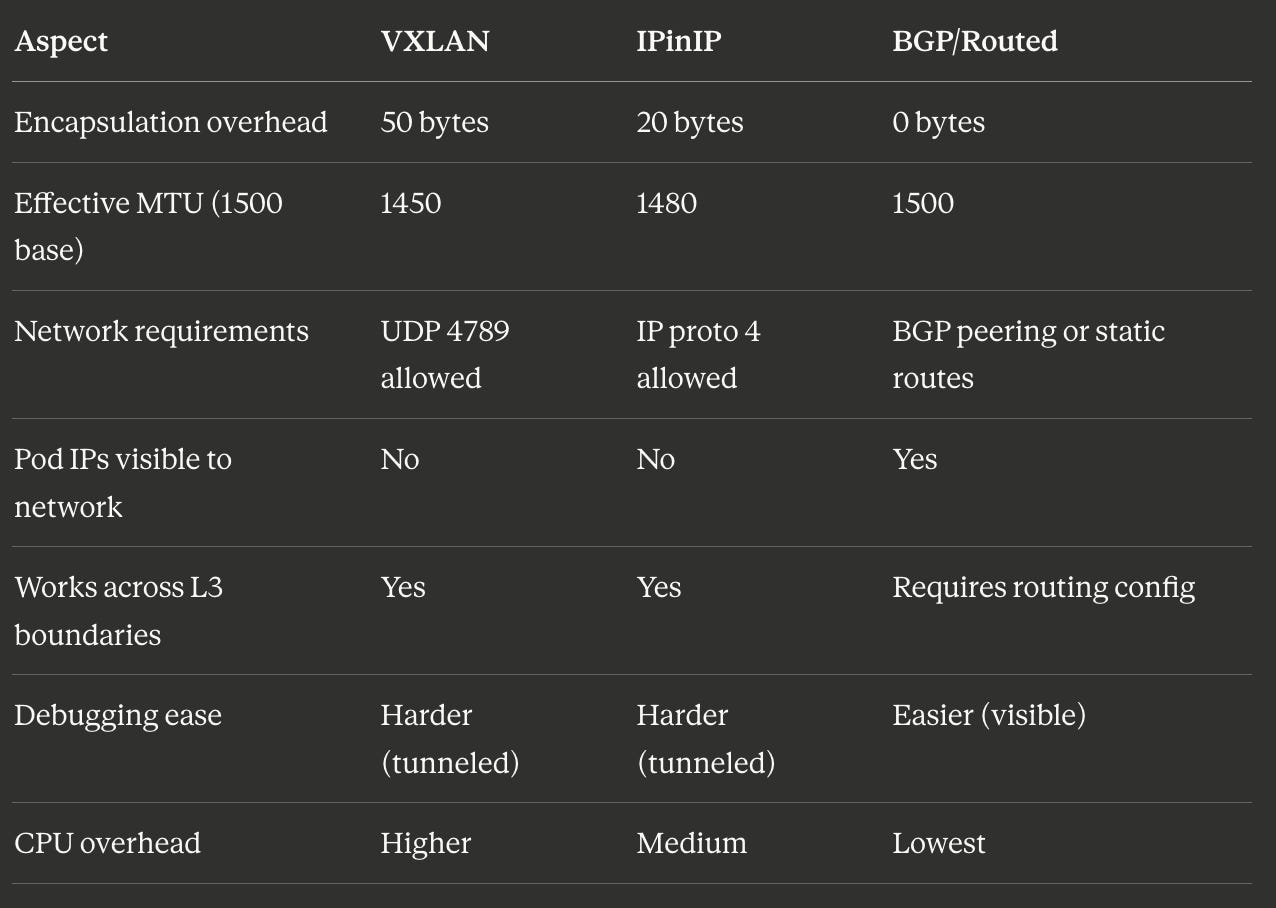
Comparing Approaches
Here are some nerdy numbers I looked up to help you compare overhead for different approaches.
Connection Tracking
Regardless of the approach, the Linux connection tracking system (conntrack) maintains state for TCP and UDP flows. This is important for return traffic (and stateful firewalling).
# View connection tracking entries
sudo conntrack -L | grep 10.244.0.5

# Output:
# tcp      6 117 TIME_WAIT src=10.244.0.5 dst=10.244.1.5 sport=45678 dport=8080
#          src=10.244.1.5 dst=10.244.0.5 sport=8080 dport=45678 [ASSURED] use=1
The conntrack entry shows both directions of the connection
src=10.244.0.5 dst=10.244.1.5 sport=45678 dport=8080
src=10.244.1.5 dst=10.244.0.5 sport=8080 dport=45678
which lets the kernel match return packets to the original flow.
Troubleshooting Pod-to-Pod Communication
Here is a non-exhaustive list of commands to help you troubleshoot communication problems between pods.
Check routing
# From inside a pod, check route to destination
ip route get 10.244.1.5

# Output:
# 10.244.1.5 via 10.244.0.1 dev eth0 src 10.244.0.5

# On the host, check route to remote pod CIDR
ip route get 10.244.1.5

# Output (VXLAN):
# 10.244.1.5 via 10.244.1.0 dev flannel.1 src 10.244.0.0
# Output (BGP):
# 10.244.1.5 via 192.168.1.11 dev eth0 src 192.168.1.10
Check bridge connectivity
# Verify bridge exists and has interfaces
bridge link show

# Output:
# 8: veth12345@if2: <BROADCAST,MULTICAST,UP> mtu 1450 master cni0 state forwarding
# 9: veth67890@if2: <BROADCAST,MULTICAST,UP> mtu 1450 master cni0 state forwarding

# Check bridge MAC table
bridge fdb show br cni0 | head
Check VXLAN state (overlay networks)
# Verify VXLAN interface exists
ip -d link show flannel.1

# Output:
# 4: flannel.1: <BROADCAST,MULTICAST,UP,LOWER_UP> mtu 1450 qdisc noqueue state UNKNOWN
#     link/ether 5a:2b:3c:4d:5e:6f brd ff:ff:ff:ff:ff:ff promiscuity 0
#     vxlan id 1 local 192.168.1.10 dev eth0 srcport 0 0 dstport 4789 nolearning

# Check VXLAN FDB entries
bridge fdb show dev flannel.1
Capture traffic at each hop
# Inside source pod
tcpdump -i eth0 -nn host 10.244.1.5

# On source node bridge
sudo tcpdump -i cni0 -nn host 10.244.0.5

# On source node physical interface (shows encapsulated or raw traffic)
sudo tcpdump -i eth0 -nn host 192.168.1.11  # or host 10.244.1.5 for BGP

# On source node VXLAN interface (shows inner traffic)
sudo tcpdump -i flannel.1 -nn host 10.244.1.5
Summary
Pod-to-pod communication takes different paths depending on pod locality:
Same-node: Packets traverse veth pairs and a Linux bridge. This is Layer 2 switching within the host. iptables is not involved unless NetworkPolicies are in place.
Cross-node with overlay (VXLAN/IPinIP): Packets are encapsulated with an outer header containing node IPs. The physical network only sees traffic between nodes. The inner pod IPs are hidden.
Cross-node with BGP routing: Packets are sent directly with pod IPs intact. The physical network must have routes for pod CIDRs. No encapsulation overhead.
Part 3 will trace north-south traffic: a packet from an external user through a LoadBalancer service, into the cluster, and back. This is where iptables and kube-proxy become central to the packet’s journey.